Mass flow = volume flow x density
volume flow(m3/second) = section (m²) x average speed (m/second)
For conversions or Nm3 Nm3 m3 / h m3 / hP1V1/T1 = P2V2/T2
p1 and T1 are the normal temperatures and pressures v1 is the normal volume (relaxed), P2 and T2 being the temperature and pressure of gas V2 is the volume of the compressed gas
with:
P = Absolute pressure (gauge pressure + atmospheric pressure)
V = volume
T = temperature Kelvin
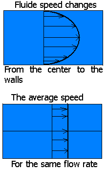
In a pipe, friction along the walls slows the fluid, so that the fluid center is at its maximum speed .. The maximum speed is generally evaluated as twice the average speed
We actually find different rates for the same pipe section. To simplify the calculations we use the average speed.

The average speed is based on the ratio :
volume flow (m3 / s) / section area (m²) = average velocity (m / s)
The average speed in the case of a constant flow leads to the continuity equation
Reynolds number Re=V.L/u
Reynolds number is a dimensionless number linking viscosity, density, and a reference length, to the speed.
Re = ((average speed) x (reference length)) / (kinematic viscosity of the fluid)
or
Re = ((density) x (average speed) x (reference length)) / (dynamic viscosity of the fluid)
The Reynolds number is used to determine the flow regime, Laminar, Transitional and Turbulent and equations to use.
The reference length can be :
The pipe diameter (for conduits)
For the Study drag unshaped geometric body, this length reference is the width of the end face (perpendicular to flow)
For the study of the lift and drag of profiled bodies, the reference surface is the maximum projected area, this length is measured parallel to the flow.
For the study of friction drag of flat plates, the reference surface is the length of the wetted surface, this length is measured parallel to the flow.
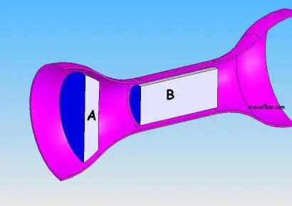
The flow continuity equation :
- Taking the average speed:
Section A x Speed A = Section B x Speed B = constant volume flow
- we deduce the velocity at point B

The sum of the pressures and mechanical energy per unit volume, is constant along the flow tube.
or: FORMULA Bernoulli:

Pressure Kinetics + Pressure of weight + Pressure energy = constant
r is the density in Kg/m3.V is fluid velocity in m/s.
g is the gravity 9.81 m/s².
Z is the vertical drop of the pipe in meters.
P is the static pressure in pascals.
Drag is the resistance force that exerts a fluid to an object while the fluid or object are moving relative to each other. This force is opposite to and parallel to the fluid path.
The drag force is calculated from:
-
a drag coefficient Cd determined experimentally in a wind tunnel
-
the fluid velocity,
-
the fluid density,
-
and the reference surface may be different according to the object studied:
-
The front surface (projection perpendicular to the flow) if the object is not profiled.
- The surface of the wing if the object is profiled (chord*length)
-
p is the density of the fluid KG/m3
S the reference surface en m²
v the relative velocity of the fluid m/s
The frictional drag and boundary layer:
The Reynolds number L (or x) distance reference

where ρ = fluid density, μ = dynamic viscosity of fluid ν = kinematic viscosity of fluid, U= flow velocity characteristic, x = characteristic dimension of flow..
The transition from laminar to turbulent is usually expressed by a Reynolds number, local critical
In the case of boundary layer flow over a flat plate, it can vary between the following limits:

For incompressible flows on a flat plate, the critical number corresponding to xcr is::

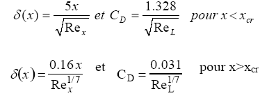
So for x <xcr the flow is laminar and turbulent if x> xcr.
The boundary layer flow over a flat plate, is a laminar flow for x <xcr, and turbulent flow for x> xcr,
Mecaflux calculating the thickness limit and Cd layer using appropriate expressions for these two flow patterns:


With drag coefficient Cd and Fd drag in Newtons
The lift is calculated as follows: :
-
coefficient measured in the wind tunnel called CL or lift coefficient
-
Wing area (in the case of the aerodynamics or hydrodynamics it is not the midship or front surface which serves as a reference for calculations)
-
Speed
-
density of fluid.
CL or lift coefficient is measured in the wind tunnel and there are databases available for many profiles of speed and different impacts the lift is needed to fly the wing with its load force, it is related to the drag, which will be compensated by a thrust at least equal to take off
Lift in Newtons
p is the density KG/m3
S is the wing area (chord*Length) m²
v relative speed of fluid m/s
The major head loss represent energy losses due to friction of the fluid in a conduit of constant section. they are expressed in fluid heights (in meters) and in pascals.
DH is the pressure drop in fluid meter column
ll is the major head loss coefficient

V is the average flow velocity
D is the diameter of the duct
L is the length of the duct
DH is the pressure drop in fluid meter column
l is the minor head loss coefficient

V is the average flow velocity
Colebrook-White formula is operable to evaluate the coefficient of major head loss in the conduits for all values of the Reynolds number- l is the major head loss coefficient,
- Re is the Reynolds number
- e = rugosity (average size of asperities of the wall mm)

MECAFLUX using this equation for Re > 105
Blasius
This formula is used to evaluate the coefficient of losses in turbulent flow moderate: (2000 < Re < 105)
l is the major head loss coefficient ,
Re is the number of Reynolds

Poiseuille:
This formula is used to evaluate the coefficient of losses in laminar flow: (Re < 2000)l is the major head loss coefficient ,
