Sizing fluids networks is mainly in calculating the head loss, and pumps that suits the best to provide the desired flow rate.
The aeraulic and hydraulic systems are sensitive to size, power consumption, operating, maintenance and installation costs are determined by the pump turbine or fan to install, but also by the conduits. Pipe sizes, depending on the imposed flow, determine the pressure drop, and therefore the power consumption of the pump / fan or energy output of the hydraulic turbine.
When the network is complex, and that the fluid can take several paths, it will opt for the easy way (with minimum pressure drop). To make sure you can control the flow after a stream separation, you must place the valves, whose aperture setting will adjust the flow rate in each branch. A phase adjustment network, is expected after installation of valves.
Mecaflux standard is sufficient to study a simple network, But for detailed, frequent, or networks of branched fluid studies, we save time by using Mecaflux Pro3D: fluid networks design with Mecaflux Pro3D
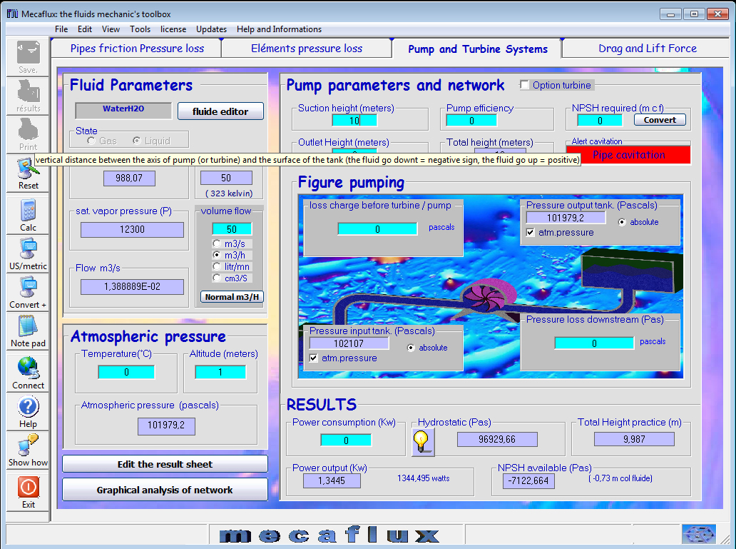
With Mecaflux standard, the parameters of a pumping system or turbine are designed simply with pumps and turbines tab. The flow parameters, head loss, cavitation, output power, power consumption, efficiency, hydrostatic head ... are updated every time you change the data.
It is in this tab you enter the major and minor losses, calculated in your pumping system or turbine to assess the power of your pump, check if it does not cavitate or evaluate the power a turbine will produce....
