To model and embed a junction and separation (tee or y fittings) in a branch portion of a network of fluid, Mecaflux standard provides a simplified method to cover all the cases encountered.
head loss calculation in junction and separation (tee or y fittings) in fluids networks , can be useful if you want to compare the pressure drop of two branch portions of a network. (Reminder: The flow in each branch / segment of an separation of stream, meet the condition of equal pressure drop in each downstream branch, together with the condition : total of the downstream flows = flow upstream. If two conditions are met we solved the flow of each branch)
- If you frequently need to modelize branched networks mecaflux "pro 3D Networks" is better suited.
Start by recalling that a segment has a given flow rate which remains constant throughout its length. If there is a flow rate change (separation or junction of flows), there is change of segment. This implies that a connection must only be in the first or last position of a segment...
7 objects fittings are available in the tab "elements pressure losses", under the category "fittings":
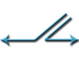
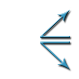
| Junction 135° | 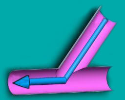 |
(plus or minus 20 degrees) |
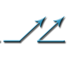
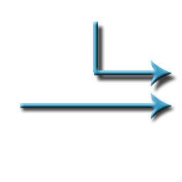
| output 135° | 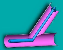 |
(plus or minus 20 degrees) |
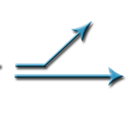
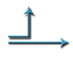
| input ou output 45° | 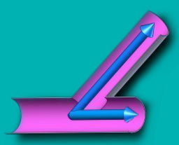 |
(plus or minus 20 degrees) |
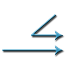
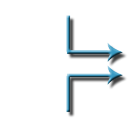
| Passage 135 ° | 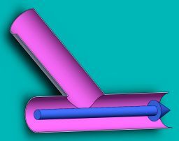 |
(plus or minus 20 degrees) |
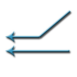
| Passage 45° | 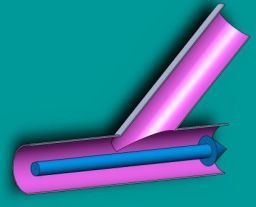 |
(plus or minus 20 degrees) |
| input ou output 90° | 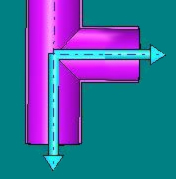 |
(plus or minus 20 degrees) |
| Passage 90° | 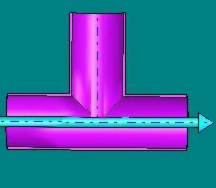 |
(plus or minus 20 degrees) |
Combinations of these 7 connections objects facility allows to model all 14 situations, separation and reunions fluid stream, gas or liquid:
reunions fluid stream |
Separations fluid stream |
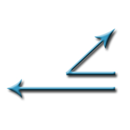
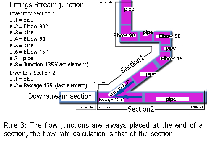
1: Junction 135° + Passage 135 ° (fittings placed at the end of segment) |
2: Junction 135° + Junction or output 45 (fittings placed at the beginning of segment) |
 = + = + |
 = + = + |
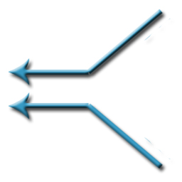
3: output 135° + Junction or output 45° (fittings placed at the end of segment) |
4: output 135° + Passage 135 °(fittings placed at the beginning of segment) |
 = + = + |
 = + = + |
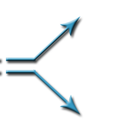
5: Junction or output45 + Passage 135 ° (fittings placed at the end of segment) |
6: Junction or output 45 + Passage 135 °(fittings placed at the beginning of segment) |
 = + = + |
 = + = + |
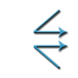
7:Junction 135° +Junction 135° (fittings placed at the end of segment |
8: output 135° +output 135°(fittings placed at the beginning of segment |
 = + = + |
 = + = + |
9: Junction or output 45 + Junction or output 45 (fittings placed at the end of segment) |
10: Junction or output 45 + Jonction or output 45 (fittings placed at the beginning of segment) |
 = + = + |
 = + = + |
11: Junction or output 90° + Passage 90° (fittings placed at the end of segment) |
12: Junction or output 90° + Passage 90°(fittings placed at the beginning of segment) |
 = + = + |
 = + = + |
13 : Junction or output 90° + Junction or output 90° (fittings placed at the end of segment) |
14: Junction or output 90° + Junction or output 90° (fittings placed at the beginning of segment) |
 = + = + |
 = + = + |
Modeling fittings is subject to three rules that evaluate all the cases encountered Exemple:
In reality the connection may have different diameters, to model these cases, insert cones, narrowing or widening to reduce the diameter to the fitting's size.
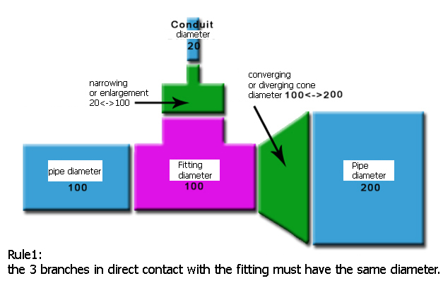
Rule 1: 3 branches in direct contact with the fitting must have the same diameter.
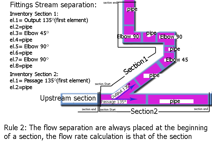
Rule 2: The flow separation are always placed at the beginning of a section, the flow rate calculation is that of the section
If you follow these basic rules, calculations of pressure losses connecting sections, of all situations encountered is possible